|
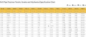
Drill Pipe Premium Tensile, Grades & Mechanical SpecificationThe Drill Pipe Premium Tensile, Grades and Mechanical Specification Chart is useful for determining the physical dimensions and mechanical properties of the drill pipe. Such physical dimensions include size, length, wall thickness, thread configuration, and diameter. The mechanical property tells about the grade and the strength range for each grade. Knowing the drill pipe specs can help a petroleum engineer or technician properly select a drill pipe, know the standards, and conduct a successful drill. Drill Pipe Premium Tensile, Grades and Mechanical Specification Chart
Drill Pipe Premium Tensile, Grades and Mechanical Specification Chart
Drill Pipe Premium Tensile Chart DetailsThe table shows the following specifications of the drill pipe: Specification sheet It details the pipe body specs such as the outer diameter, wall thickness (in), nominal ID, tensile strength (lbs), torsional strength (ft-lbs.), burst capacity (pounds per square inch), and collapse capacity (psi). The sheet also shows the detailed specs of the tubular assembly (the proper design, selection and installation of tubing string), connection, and elevator shoulder. Outside diameter (OD) Specified in inches or a fraction of an inch, the OD is the distance between the top to bottom, right to left from the pipe’s outer edges. Grade This defines the minimum yield strength and tensile strength which are both measured in pounds per square inch. It also provides the required specs for the properties of the material. As shown in the table of Tensile and Mechanical Specification of Drill Pipe premium, each grade has its own yield strength. Such grade specification can indicate the suitability of each drill pipe grade. For instance, Grade E is used in medium deep wells from 10, 000 to 15, 000 feet. The higher the steel grade, the less resistant it is to the corrosion caused by hydrogen sulfide or H2S. On the other hand, the higher the drill pipe strength (anti-extrusion strength, tensile strength, yield strength, and anti-extrusion strength), the higher the steel grade. Grades S, X and G constitute the high strength drill pipe grades. To calculate the yield strength in pounds, one must know the cross-sectional area via the drill pipe classes. The table of Drill Pipe Premium Grades, Tensile and Mechanical Specification also shows the following grades:
Range It classifies the length of each drill pipe joint based on the American Petroleum Institute’s specs; the API range constitutes 1 (length in feet: 18-22), 2 (27-30) and 3 (38-45). Wall It specifies the wall thickness of drill pipe measured in inches. Nominal This refers to the pipe body weight per unit length. Adjusted It refers to the weight per foot of pipe that includes the upset (the thickened wall on the tube ends) without the tool joint based on 29.4 ft length. Tool Joint or TJ It is a threaded joint of drill pipe; it is differentiated by the pin or the male threaded connection and the female threaded connection known as the box. Tool Joint Internal Diameter TJ ID (in) It specifies the internal diameter of the tool joint; the torsional strength ratio establishes the tool joint OD and ID Tube Outside Diameter TJ OD It refers to the distance between the inner wall either from right to left or top to bottom. Tool Joint Yield (ft-lbs) It is measured in feet and pounds. It describes the torsional strength of the tool joint. Premium Tube Tensile (lbs) This describes the strength of premium tubes whenever a tensile stress is applied, up to the point that the tube reaches its structural failure or breaking. Drill Pipe Premium Tensile Chart Abbreviations:
Go here if you are looking for the Drill Pipe Capacity and Displacement Chart. The Oilfield Equipment related post Drill Pipe Premium Tensile Chart is from Flowtech Energy. Looking for Oilfield Equipment including New, Used, Remanufactured and Surplus Oilfield Supply, check out our inventory or call our toll free number at 877-645-6693 for more information. from https://www.flowtechenergy.com/charts/drill-pipe-premium-tensile-grades-and-mechanical-specification-chart/
0 Comments
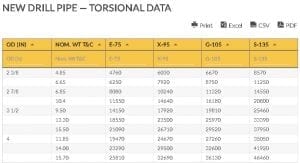
Drill PipeDrill pipe is a thick-walled and hollowed piping that carries and transfers torque and drilling fluid through the wellbore and to the drill bit up to the drilling rig. A drill pipe can endure distortion, bending, vibration, external, and internal pressure as it lifts the bottom hole assembly. Drill pipe features a threaded end in the pipe section called the tool joint. New Drill Pipe Torsion, Tensile, and Pressure Chart DataAs an example, drill pipe with an outer diameter of 2 3/8 inch, a nominal wall thickness of 4.85 lb/ft, and a grade of E-75 shows a torsional yield strength of 4760 ft – lb. Similar data is shown for other nominal wall thickness and grades in the table below: NEW DRILL PIPE — TORSIONAL DATA
NEW DRILL PIPE — TORSIONAL DATA
NEW DRILL PIPE — TENSILE DATA
NEW DRILL PIPE — TENSILE DATA
NEW DRILL PIPE — COLLAPSE PRESSURE DATA
NEW DRILL PIPE — COLLAPSE PRESSURE DATA
NEW DRILL PIPE — INTERNAL PRESSURE DATA
NEW DRILL PIPE — INTERNAL PRESSURE DATA
New Drill Pipe Torsion, Tensile and Pressure Data Chart Abbreviations:
The chart details the columns of New Drill Pipe Tensile and Torsion Pressure Data, as well as the outer diameter size (measured in inches) and nominal wall thickness (measured in pound and feet). Torsional data refers to the measurement of torsional yield strength that is the amount of rotating and twisting force that a pipe can withstand before it reaches its structural failure, which is basically the breaking or twisting point. This is based on shear strength, which is equal to 57.7% of nominal wall thickness and minimum yield strength. Collapse data measures the collapse rating pressure in psi of each drill pipe grade. Collapse happens when the differential between internal and external pressure exceeds the collapse rating pressure of the drill pipe. Internal pressure data describes the burst or internal yield pressure of the drill pipe where pressure from within surpasses the pressure loading. Burst can occur in various situations such as pressure test casing and/or tubing, pumping operation, and well control. Different pipe grades feature various ratings where grade H-40 claims a high maximum internal pressure rating of 16.40, measured in pound per square inch or psi and conversely the grade 180 at 11.23. Each grade in the New Drill Pipe Torsion, Tensile and Pressure Data shows different outer diameter ratings, with increments starting from the shortest (2 3/8 inches) up to the largest size (6 5/8 inches) and the corresponding nominal wall thickness of the drill pipe grade. Go here if you are looking for the Drill Pipe Premium Tensile, Grades and Mechanical Specification Chart. The Oilfield Equipment related post New Drill Pipe Torsion, Tensile and Pressure Data Chart is from Flowtech Energy. Looking for Oilfield Equipment including New, Used, Remanufactured and Surplus Oilfield Supply, check out our inventory or call our toll free number at 877-645-6693 for more information. from https://www.flowtechenergy.com/charts/new-drill-pipe-torsion-tensile-and-pressure-data-chart/
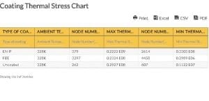
Coating Thermal Stress DiscussionThe impact of high temperature is determined through thermal stress. The thermal stress, which develops on the pipe wall, is also a factor in considering the ideal pipe material and size. In thermal analysis, two coatings are highly considered: the Electroless Nickel Phosphorous (EN-P)and Fusion Bonded Epoxy (FBE). EN-P is a method that deposits noble metal on an active surface with less noble metal by putting an agent without utilizing electrical energy. This alloy coating is proven to be more sensitive compared to FBE. This means that there is a large possibility of stress corrosion cracking. It also has different types: High Phosphorus This coating is non-magnetic and has the lowest internal stress, which makes it the best EN (Electroless Nickel). Medium Phosphorus This coating has a melting point of 1,000 degrees C and has a faster plating rate, which leads to reduced cost compared to high phosphorous coating. Low Phosphorus This coating is a type of Electroless Nickel that is less ductile due to the presence of micro-crystalline. It is also the least corrosion resistant, yet it is more conductive in contrast to high and medium phosphorus. Fusion Bonded Epoxy, on the other hand, is a powder coating that is originally a thermoset polymer. This has been recognized globally, since it does not only provide protection against corrosion but also enables any liquid to flow smoothly. Coating Thermal Stress BenefitsThe two coatings commonly used (EN-P and FBE) offer benefits that make customers opt for such products. Compared to the other coatings, EN-P is less porous and makes steel pipes corrosion- resistant and durable. This can be applied with little compressive stress. In addition, it does not require electricity during operation, making it cost-effective. The operation also requires less coat and equipment, yet still creates a durable and high-quality pipe finish. The FBE coating has strong adhesion on the surface. It also has high penetration resistance against harmful elements. In addition, it is highly reliable against soil stress, impact, water absorption, and abrasion. Best of all, FBE has long-lasting mechanical and chemical resistance under different temperatures and seasons Coating Thermal Stress Chart
Coating Thermal Stress Chart
In the Table for Coating Thermal Stress, EN-P stands for Electroless Nickel Phosphorous coating while FBE means Fusion Bonded Epoxy coating. Coating Thermal Stress Chart Abbreviations:
Go here if you are looking for the Coating Thermal Performance Chart. The Oilfield Equipment related post Coating Thermal Stress Chart is from Flowtech Energy. Looking for Oilfield Equipment including New, Used, Remanufactured and Surplus Oilfield Supply, check out our inventory or call our toll free number at 877-645-6693 for more information. from https://www.flowtechenergy.com/charts/coating-thermal-stress-chart/
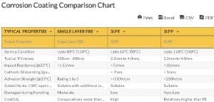
Corrosion Coating Comparison Chart presents information comparing different properties like Single Layer FBE, 3LPE, and 3LPP. Most of the time, a corrosion coating helps protect metal materials from breakage due to detrimental factors such as moisture, oxidation, and harmful industrial chemicals. This coating is added to the surface and acts as a barrier to impede chemicals and corrosive materials. Corrosion Coating Comparison DiscussionThis is significantly helpful in any industry, especially the field of gas and oil. It helps maintain the efficiency and extends the longevity of the pipe used for transporting fluids. Types of Corrosion CoatingSingle Layer FBE It is also known as Fusion Bonded Epoxy coating. It is a powder coating commonly used to give security to steel pipe and pipelines. This coating is originally a thermoset polymer. This environmentally safe coating is applied on the surface of the pipe create a durable barrier. For the coating to be efficient, it has to reach a target temperature that ranges from 180 to 250 Celsius. 3LPE and 3LPP These corrosion coatings are multilayer coatings that consist of three functional elements. The first element is the FBE that works as a primer and should be 150 microns thick. It is followed by an adhesive called copolymer with 200 microns thickness, and polyethylene as the last layer which gives durable protection. The standards and codes for these are DIN 30670 or CAN/CSA Z245.21 and ISO 21809-1. Corrosion Coating BenefitsAside from keeping the pipe safe, corrosion coatings have other benefits to customers. 1. It eliminates large repair expenses. Pipe that are damaged greatly due to chemical factors are subject to an expensive replacement operation. However, opting for this product can reduce the cost by giving extra protection. 2. It avoids delay in operation. As pipe replacement or maintenance takes hours to complete, it will result in delayed operation. Coatings will help prevent that delay of production. 3. It results in less friction. For some operations, friction can be the cause why parts are moving slowly. Having a corrosion barrier will minimize the friction between surfaces. 4. It is non-flammable. Some anti-corrosion agents are made with a flame spread rate of 0. This means that the product is fireproof. Corrosion Coating Comparison Chart
Corrosion Coating Comparison Chart
Corrosion Coating Comparison Chart Abbreviations:
Terms Used for Corrosion Coating Types
Go here if you are looking for the Coating Thermal Stress Chart. The Oilfield Equipment related post Corrosion Coating Comparison Chart is from Flowtech Energy. Looking for Oilfield Equipment including New, Used, Remanufactured and Surplus Oilfield Supply, check out our inventory or call our toll free number at 877-645-6693 for more information. from https://www.flowtechenergy.com/charts/corrosion-coating-comparison-chart/
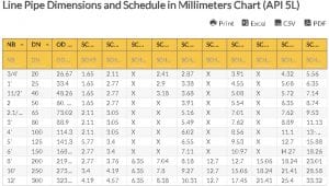
Line Pipe Dimensions and ScheduleThe line pipe dimensions and schedule is in line with a set of specifications to differentiate line pipe that can be placed under low or extreme pressures and operations. The normal bore (NB) is the American way of describing the dimension of the line pipe. NB and the nominal pipe size (NPS) are also used interchangeably to define the size of the pipe. For example, a pipe with NPS of 7 can be identified as a 7-inch pipe. There are certain details that must be considered, like the fact that the NPS of a pipe ranging from 1/8” to 12” is neither the inner diameter (ID) nor the outer diameter (OD). For line pipe with 14” and higher NPS, this is the same as the line pipe’s outer diameter (OD). Line pipe schedule is one more non-dimensional number that can identify the line pipe. The schedule of the line pipe informs oil industry operators about the wall thickness of the pipe. Such is categorized as standard weight (STD), extra-heavy (XH) or extra-strong (XS), and double extra-heavy (XXH) or double extra-strong (XXS). Different organizations, including the American Petroleum Institute (API), have made various revisions and additions to the line pipe schedule through the years to cope with the growing oil and gas industry. Line Pipe Dimensions and Schedule of API 5LThe line pipe dimensions and schedule of API 5L is provided by the API to certify the quality of the pipe for the transport of oil and natural gas. Regulation of the usage of Standard Grade A, Grade B, and Grade X pipe is included in the API standards. Both seamless and electric resistance weld (ERW) pipe are available in the API 5L specifications. Line Pipe Dimensions and Schedule RelevanceLine pipe dimension is characterized through the outer diameter (OD,) wall thickness (WT), and length of the pipe. These measures help in the calculation of the pipe weight, pipe cost per meter or per foot, and the total pressure that the pipe can endure. Likewise, line pipe schedule is a significant specification for oil and gas industry operators because it allows them to determine whether the pipe can be installed inside their casting and screen or not. Line Pipe Dimensions and Schedule in Millimeters Chart (API 5L)
Line Pipe Dimensions and Schedule in Millimeters Chart (API 5L)
The line pipe dimensions and schedule of the API 5L pipe provides the following information: nominal bore (NB), diameter nominal (DN), outer diameter (OD) in millimeter, and pipe schedule. NB is approximately related to the inner diameter (ID) of the line pipe, while OD remains constant for each NB. Each pipe size is presented with various schedules or wall thickness. The heavier the line pipe’s schedule is, the smaller the bore appears. Line Pipe Dimensions and Schedule in Millimeters Chart Abbreviations:
Go here if you are looking for the Line Pipe Dimensions and Schedule in Inches Chart (API 5L). The Oilfield Equipment related post Line Pipe Dimensions and Schedule in Millimeters Chart (API 5L) is from Flowtech Energy. Looking for Oilfield Equipment including New, Used, Remanufactured and Surplus Oilfield Supply, check out our inventory or call our toll free number at 877-645-6693 for more information. from https://www.flowtechenergy.com/charts/line-pipe-dimensions-and-schedule-in-millimeters-chart-api-5l/
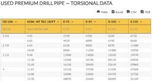
Used premium drill pipe torsion, tensile, and pressure data can be helpful in determining the limitations of a certain pipe. This will become a guide on what type of pipe to use in certain situations. For premium pipe, a higher torsion, pressure, and tensile strength implies that it would have less chances of breakage, affecting its efficiency and longevity due to tension and other factors. Used Premium Drill Pipe Torsion, Tensile, and Pressure DiscussionTorsion, pressure, and tensile strength are important factors to consider in installing pipe. It is relevant to know these terms further. Torsional strength refers to the capability of a material to resist loads that cause the pipe to twist. This is the maximum strength and torsional stress a material is subjected to during torsional loading. It is also termed as shear or rupture strength. The calculation of the strength depends on whether the pipe is solid or hollow. Tensile strength relates to the pipe’s elasticity. It refers to the material’s strength to withstand pulling force without any damage. Pressure strength is the ability of a material to withstand force that reduces a pipe’s size. Torsion, Tensile, and Pressure Strength FormulaIn a study of the pipe’s strength, these three factors are analyzed and calculated independently. Torsional Strength: T= HP x 5250/RPM T= torque delivered to DP, ft-lb HP = the horse power exerted to make the pipe rotate RPM = revolution per minute Tensile Strength lb. = psi x in2 lb = tensile strength psi = minimum yield strength in2 = cross sectional area Pressure Strength: P = (2*S*T)/((O.D.-2*T)*SF) P = fluid pressure T = pipe wall thickness S = material strength O.D. = pipe outside diameter SF = safety factor Used Premium Drill Pipe Torsion, Tensile and Pressure BenefitsThe Premium Class pipe has been used globally and has become a norm in the industry for drilling compared to Class 2. This is due to the significant difference in the minimum tool joint outside diameter, maximum allowable slip out, and tube wall thickness. USED PREMIUM DRILL PIPE — TORSIONAL DATA
USED PREMIUM DRILL PIPE — TORSIONAL DATA
USED PREMIUM DRILL PIPE — TENSILE DATA
USED PREMIUM DRILL PIPE — TENSILE DATA
USED PREMIUM DRILL PIPE — COLLAPSE PRESSURE DATA
USED PREMIUM DRILL PIPE — COLLAPSE PRESSURE DATA
USED PREMIUM DRILL PIPE — INTERNAL PRESSURE DATA
USED PREMIUM DRILL PIPE — INTERNAL PRESSURE DATA
Used Premium Drill Pipe Torsion, Tensile and Pressure Data Chart Abbreviations:OD – Outer Diameter T & C – Threaded and coupled ends in – inches lb/ft – pounds per feet ft-lb – foot-pounds lb – pounds psi – pounds per square inch Metric System: O.D X 25.4 = mm I.D x 25.4 = mm Wall x 25.4 = mm Go here if you are looking for the New Drill Pipe Torsion, Tensile and Pressure Data Chart. The Oilfield Equipment related post Used Premium Drill Pipe Torsion, Tensile and Pressure Data Chart is from Flowtech Energy. Looking for Oilfield Equipment including New, Used, Remanufactured and Surplus Oilfield Supply, check out our inventory or call our toll free number at 877-645-6693 for more information. from https://www.flowtechenergy.com/charts/used-premium-drill-pipe-torsion-tensile-and-pressure-data-chart/
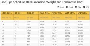
For example, Pipe Size 2.000 with Schedule 80 has 0.218 actual wall thickness. Relationship among the Dimension SpecificationsThe outside diameter (mm), wall thickness, and weight increment, as the pipe nominal size increases, except for the outside diameter measured in inches. Pipe Schedule 100 Dimension, Weight, and Thickness ChartThe Pipe Schedule 100 Dimension, Weight, and Thickness Chart shows the numerical and dimension specifications (in rows) and descriptions (in columns) of the pipe. The table is useful for specifying the accurate measurements of each nominal size. Line Pipe Schedule 100 Dimension, Weight and Thickness Chart
Line Pipe Schedule 100 Dimension, Weight and Thickness Chart
Column DescriptionsThe column of Line Pipe Schedule 100 Dimension, Weight, and Thickness specifies each of the values below: Nominal size refers to the approximate inside diameter, sizes, and thickness. The nominal size of pipe in inches does not reflect the actual size. Nominal size is also a trade size used for trade descriptions. For instance, a pipe measured 2” nominal size is equal to 2.067 inches. Outside Diameter (OD in inches) is the measurement of the pipe’s outer diameter. To calculate the OD: OD = ID + Wall Thickness (2x) The wall thickness stays the same for a given nominal pipe size. Outside Diameter (OD in mm) is the OD in millimeter. As the nominal size increases, so does the outside diameter. Wall thickness (inches and mm) is expressed in pipe schedule or SCH. To calculate the wall thickness, here’s the formula: (OD – ID) / 2 Where OD is the outside diameter and ID is the inside diameter For instance, 5 – 2 /2 = 1.5 Subtract the outside diameter to the internal diameter and divide the result by 2. Weight (lb/ft) (kg/m) refers to the weight per foot of any pipe wall thickness and size. The weight increases as the nominal size, outside diameter, and wall thickness increase. The weight per lb/ft and kg/m increases as the pipe nominal sizes increase. To calculate, use the following formula: Pipe weight = Volume = pi (internal diameter – external diameter) / cross-sectional area X length Volume = (in meters) X (the equivalent unit of a specific metal type, for instance a unit of cast iron is 7200 kg/m3 while for steel it’s 7859kg/m3) Pipe Schedule 100 Dimension, Weight, and Thickness Chart Abbreviations:
Go here if you are looking for the Line Pipe Dimensions and Schedule in Millimeters Chart (API 5L). The Oilfield Equipment related post Line Pipe Schedule 100 Dimension, Weight and Thickness Chart is from Flowtech Energy. Looking for Oilfield Equipment including New, Used, Remanufactured and Surplus Oilfield Supply, check out our inventory or call our toll free number at 877-645-6693 for more information. from https://www.flowtechenergy.com/charts/line-pipe-schedule-100-dimension-weight-and-thickness-chart/
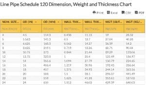
Line Pipe ScheduleThe term “schedule” in Line Pipe Schedule 120 Dimension, Thickness, and Weight refers to the wall thickness of the pipe used in the oil and gas industry. As the wall thickness increases, the schedule number rises. Higher schedule pipe such as 100 and 120 have the same exterior diameter as 40, 6, and others. However, the higher schedules 100 and 120 have extra thickness in their interiors. The American Society of Mechanical Engineers (ASME) committee developed the standard pipe schedules to save cost. The most popular schedule is 30, while the least used are 5, 60, 100, 120, and 140. The pipe schedule has the following approximate value: Schedule Number = (1,000) (P/S) For instance: P = PSI or internal working pressure S = allowed stress or PSI of the construction material To determine the pipe schedule: Inside Diameter / Wall Thickness The pipe schedule 120 is a thickness designator that means schedule 120 is thicker than schedule 100. An increase in service pressure can increase the pipe’s schedule. Relationship among Dimensional ValuesThe increase in nominal size also increases the outside diameter (mm), wall thickness (mm), and weight (lb/ft) or (kg/m), except for the outside diameter (inches) that stays the same. Line Pipe Schedule 120 Dimension, Weight and Thickness ChartThe table for Line Pipe Schedule 120 Dimension, Thickness and Weight is useful for determining the exact numerical measures or dimensions such as the nominal size, outside diameter, wall thickness, and weight of the Pipe Schedule 120. Line Pipe Schedule 120 Dimension, Weight and Thickness Chart
Line Pipe Schedule 120 Dimension, Weight and Thickness Chart
Dimensional ValuesThe Thickness, Weight Dimension Table for Line Pipe Schedule 120 constitutes the dimensional values (in columns) for each nominal size (inches) in rows. The nominal size (inches) refers to the non-approximate size for the purpose of description or trade. In piping, it’s called the nominal pipe size that is equal to the inside diameter (ID). An increase in wall size decreases the inside diameter. The outside diameter (inches) is the pipe measurement from left to right or top to bottom that originates from the pipe’s outer wall. Outside Diameter = Circumference / pi (3.1415) Wall thickness (inches and millimeters) is specified by the term schedule. The wall thickness is the measurement (inches) of the pipe’s wall. Wall Thickness = Inside Diameter – Outside Diameter / 2 Weight refers to the pipe’s weight measured in pounds per feet or kilograms per meter. Here is the formula to calculate it: A copper tube, for instance, has a formula of (Outer Diameter – Wall Thickness) x thickness (mm) x -0.02796 x length (m). Line Pipe Schedule 120 Dimension, Weight and Thickness Chart Abbreviations:
Go here if you are looking for the Line Pipe Schedule 100 Dimension, Weight and Thickness Chart. The Oilfield Equipment related post Line Pipe Schedule 120 Dimension, Weight and Thickness Chart is from Flowtech Energy. Looking for Oilfield Equipment including New, Used, Remanufactured and Surplus Oilfield Supply, check out our inventory or call our toll free number at 877-645-6693 for more information. from https://www.flowtechenergy.com/charts/line-pipe-schedule-120-dimension-weight-and-thickness-chart/
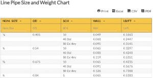
Line Pipe Size and WeightLine Pipe Size and Weight Chart is a table of information that provides precise structural details of certain pipe. It gives customers an overview of how efficient the pipe can be. In the gas and oil industry, line pipe are widely utilized to transport fluids such as petroleum, natural gas, and crude products. The pipe usually carries a certain product. To ensure that the material is suitable for a certain project, it is manufactured under the standards of the American Petroleum Institute. The main focus of the institution is to create a series of quality standards in accordance with environmental and legislative guidelines. Line Pipe Size and Weight DiscussionFor line pipe, the institute has mandated the industry to follow API Specification 5L. Its production involves the process of using micro-alloy heating treatment. This specification states that the pipe will be used to transport products from the gas and oil industry. Moreover, it helps enterprises to develop the material’s cost-effectiveness and efficiency. Such field manufactures two kinds of line pipe: welded line pipe and seamless line pipe. Pipe have different sizes and weights. This is determined by its NPS, O.D, and Pipe Schedule. NPS is the globally followed standard size for different pipe used for temperatures and pressure ranging from high to low. The term “nominal” refers to the diameter of the material. Pipe Schedule is used to determine the wall thickness of different pipe sizes. The SCH uses the standards of the American Society of Mechanical Engineering. There are 11 new schedules developed: 5, 10, 20, 30, 40, 60, 80, 100, 120, 140, & 160. SCH 40 is the most popular. Line Pipe Size and Weight BenefitsLine pipe are widely used for liquid transportation because of the various benefits they offer. For instance, opting for line pipe will significantly curtail the transportation cost. This reason alone captivates the interest of customers. Another reason is that maintenance is not necessary once it is installed as the material is made to be highly resistant to chemicals elements and corrosion. Investing in line pipe can also be a great decision as this material is designed to last for more 20 years. Line Pipe Size and Weight Chart
Line Pipe Size and Weight Chart
Line Pipe Size and Weight Chart Abbreviations:
Metrification Formula
Go here if you are looking for the Welded and Seamless Steel Pipe Schedule Weight Chart. The Oilfield Equipment related post Line Pipe Size and Weight Chart is from Flowtech Energy. Looking for Oilfield Equipment including New, Used, Remanufactured and Surplus Oilfield Supply, check out our inventory or call our toll free number at 877-645-6693 for more information. from https://www.flowtechenergy.com/charts/line-pipe-size-and-weight-chart/
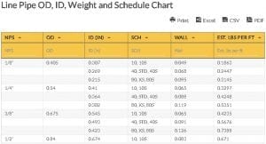
Line Pipe OD, ID, Weight and ScheduleNPS stands for Nominal Pipe Size, which is basically the number that represents the pipe size. For instance, a pipe that measures six inches has a nominal pipe size of six inches. However, that is not definitive, as it still depends on the size of the pipe. For sizes NPS 14 and higher, NPS is the same as the OD or Outside Diameter. The concept is easier to understand when you have knowledge on how line pipe is manufactured. For NPS 1/8 to NPS 12 pipe, the outside diameter is fixed. This means that if there is any increase in wall thickness, it would be the ID or inside diameter that will decrease. In this case, the line pipe ID is equal (approximately) to the NPS. For sizes bigger than NPS 12, NPS stands for the actual OD of the line pipe. Any wall thickness variation will not affect NPS, just the ID or inside diameter. Pipe Schedule ChartTo understand the pipe schedule better, here is the Line Pipe OD, ID, Weight and Schedule Chart: Line Pipe OD, ID, Weight and Schedule Chart
Line Pipe OD, ID, Weight and Schedule Chart
Pipe Schedule DiscussionPipe schedule is the term the industry uses to describe the pipe’s thickness. ASME (American Society of Mechanical Engineers) has come up with the Schedule Number based on a modified version of Barlow’s wall thickness formula. It indicates the approximate value of the expression 1000 x P/S. The said formula is as follows: Schedule Number = P/S where P is the service pressure per square inch and S is the allowable stress per square inch 40 is probably the most well-known and most commonly used schedule. Schedule 40 is just a designator for pipe thickness. In layman’s term, schedule 40 pipe can handle a specific amount of pressure. For instance, the schedule number of steel pipe that has an allowable stress of 10,000 psi for 350 psig of working pressure would be computed this way: Schedule Number = (1,000)(350/10,000) The schedule number would be 35 or approximately 40. Pipe Schedule Chart Abbreviations:
Go here if you are looking for the Line Pipe Schedule and Thickness Chart The Oilfield Equipment related post Line Pipe OD, ID, Weight and Schedule Chart is from Flowtech Energy. Looking for Oilfield Equipment including New, Used, Remanufactured and Surplus Oilfield Supply, check out our inventory or call our toll free number at 877-645-6693 for more information. from https://www.flowtechenergy.com/charts/line-pipe-od-id-weight-and-schedule-chart/ |
About UsOur goal and our mission is to provide a solid and dependent structure to support your companies needs. We have over thirty years supplying and supporting industrial drilling equipment for companies around the world. In order to support and provide the best customer experience we focus on you, the customer, to offer a full turnkey solution for whatever your business needs. Our products fused with our customer service will bring you a sophisticated, well oiled business process that can fit any business need. ArchivesNo Archives Categories |
 RSS Feed
