|
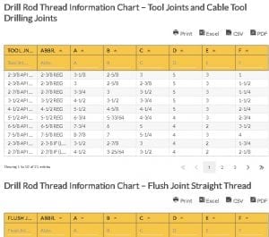
Drill rod thread basically differs for every type of drill rod. Threads of standard drill rods come in aluminum or mid-weight steel, allowing ergonomic flexibility that provides better handling capacities even on most demanding applications. Other conditions, including mineral explorations, require rod threads that can be used with standard core barrels, just like the WJ type threads. Drill rod thread undergoes evaluation during drill rod production and drill rod couplings to ensure that high-quality steel is used and that it can hold up against drilling under the most severe environments. Drill Rod Thread TypesParallel Threaded Rods These rods have female threads at both ends of the steel tube, which can be replaced with pin-to-pin couplers. High-quality seamless carbon steel is used to produce these rods, ensuring sturdiness and uniformity. On the other hand, heat treated-alloy steel is utilized to manufacture male-threaded couplings, delivering maximum durability and wear endurance. Rotary drilling operations can best benefit from these rods. Taper Threaded Rods Both replaceable male and female tool joints are available with these drill rods; these are bolted into the rod tube. Heat-treated alloy steel is used to produce these rods to ensure utmost durability and wear resistance. Drill Rod Thread Common ProblemsRegular inspection of all machineries is implemented within the rig, looking for possible issues that can occur, such as:
Drill Rod Thread Information Chart – Tool Joints and Cable Tool Drilling Joints
Drill Rod Thread Information Chart – Tool Joints and Cable Tool Drilling Joints
Drill Rod Thread Information Chart – Flush Joint Straight Thread
Drill Rod Thread Information Chart – Flush Joint Straight Thread
Drill rod thread comes in various forms and sizes, where some are categorized under the American Petroleum Institute (API) connections and others as premium connections. API Connections Single shoulder connections are possible with these, where there is only one torque shoulder on both box and pin. These can be identified as:
Premium Connections Premium connections generally have a double shoulder. They possess an extra torque shoulder at the end of the box, and in the nose of the pin. They can handle higher torque applications and are available in various shapes and sizes:
Drill Rod Thread Compatibility Chart Abbreviations:
Go here if you are looking for the Drill Pipe Heavy Weight Chart. The Oilfield Equipment related post Drill Rod Thread Compatibility Chart is from Flowtech Energy. Looking for Oilfield Equipment including New, Used, Remanufactured and Surplus Oilfield Supply, check out our inventory or call our toll free number at 877-645-6693 for more information. from https://www.flowtechenergy.com/charts/drill-rod-thread-compatibility-chart/
0 Comments
The Coating Thermal Performance Chart (Table 1) shows various temperatures for the different days and the pipe coating studied in the Omani desert region. Table 2 shows the physical properties of crude oil from five Omani locations. It is useful for determining the temperature effects on coating and the best coating for pipes on certain temperature conditions. Coating Thermal Performance Table AnalysisThe Table for Coating Thermal Performance (Table 1) details columns for temperature zones (in rows), temperatures in the surface of coating for varying temperature zones, and the temperature for the inside pipeline. The full section or inside pipeline temperature (Celsius and Kelvin) remains constant while the surface temperature on coating increased. The temperature peaked at mid-day and dropped to negative 10 degrees Celsius in the evening. Both types of coatings (EN-P and FBE) slow down the heat transfer rate and allow effective insulation. Thermal coating is useful for reducing or preventing thermal stress and thus, increases the pipe’s life service. The EN-P coating shows lower rates of heat transfer compared to the FBE coating. The Table for Crude Oil Properties (Table 2) shows the physical property (density) of crude oil samples at various Omani locations. The five columns show the temperature and the five Omani locations – Erad, Oman Export, Receive line, Mabruk, and Zal-41. The table shows that the crude oil from Erad is the heaviest and that the lightest is from Zal 41. An increment in temperature decreases each of the oil sample’s densities. Coating Thermal Performance Chart
Coating Thermal Performance Chart
Crude Oil Properties Chart
Crude Oil Properties Chart
Legend: tT – Temperature Transducer Coating Thermal Performance Chart: Definition of TermsASTM A106 B ASTM A106 B refers to the standard pipe used in high-temperature environments. ASTM stands for American Society for Testing and Materials. Stress Corrosion Cracking (SSC) SSC refers to the crack formation growth that can cause unexpected structural failure in ductile metals such as metal pipes. Environment, metallurgy, and stress form the conditions that allow SSC. Electroless Nickel Phosphorus (EN-P) EN-P is a coating made by using a chemical bath that deposits nickel. The EN-P coating is resistant to corrosion and scratch. Fusion Bonded Epoxy (FBE) FBE is a powder-based coating with epoxy properties. It is used to protect and coat valves, steel pipeline, and piping connections. The epoxy derived its name from the “fusion bonding” process when the epoxy and the hardener react to form a solid material that adheres to the substrate. Thermal Stress Thermal stress refers to a change in the temperature of a material. A rapid change from cool to high temperature can cause cracking in some materials. Go here if you are looking for the Corrosion Coating Comparison Chart. The Oilfield Equipment related post Coating Thermal Performance Chart is from Flowtech Energy. Looking for Oilfield Equipment including New, Used, Remanufactured and Surplus Oilfield Supply, check out our inventory or call our toll free number at 877-645-6693 for more information. from https://www.flowtechenergy.com/charts/coating-thermal-performance-chart/
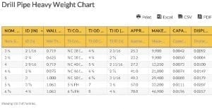
Drill pipe heavy weight is a type of drill pipe with thickened walls and longer collars compared to the standard drill pipe. This provides the heavy weight drill pipe (HWDP) with higher tensile strength. To facilitate greater support, HDWP is positioned near the topmost part of a long drill string. Drill Pipe Heavy Weight SpecificationsDrill pipe heavy weight usually functions as a transitional part from a heavy drill collar to comparatively lightweight drill pipe. The wall of an intermediate HDWP measures about one-inch-thick, beneficial in the inhibition of stress concentration at the upper portion of drill collars. Higher RPM drilling with lessened torque and differential pressure sticking is possible with the use of heavy weight drill pipe. A wear pad or unique middle upset can be seen in HDWP, allowing the tube to stay away from the hole wall, resulting in the decrease in hole drag and differential sticking glitches. Drill Pipe Heavy Weight BenefitsDirectional drilling is best applied with a heavy weight drill pipe. Directional control is made easy with reduced connection fatigue issues generic to horizontal or high-angle drilling, all credits to the ability of HWDP to bend easily. Highly sturdy heavy weight drill pipe is commonly utilized in the hole of extended reach and horizontal well to pull on the bit, more particularly in wells where there is a low ratio between the measured depth ratio and the total vertical depth. Different combinations of drill pipe with heavy weight, drill collars, and conventional drill string gear can be established to keep up with the intensity of the drilling conditions. Drill Pipe Heavy Weight Chart
Drill Pipe Heavy Weight Chart
Drill Pipe Heavy Weight – Terms and DefinitionsA Heavy weight drill pipe is the oil and gas industry’s choice for operations of intermediate weight drill stem. It has different dimensions following the requirements set, similar with the standard drill pipe.
The volume of fluid to be displaced if positioned into fluid having the lower portion closed–to prevent fluid from going inside–is the displacement for closed-ended pipe. Drill Pipe Heavy Weight Chart Abbreviations:
Go here if you are looking for the Drill Pipe Specification with Upset and Tool Joint Chart. The Oilfield Equipment related post Drill Pipe Heavy Weight Chart is from Flowtech Energy. Looking for Oilfield Equipment including New, Used, Remanufactured and Surplus Oilfield Supply, check out our inventory or call our toll free number at 877-645-6693 for more information. from https://www.flowtechenergy.com/charts/drill-pipe-heavy-weight-chart/
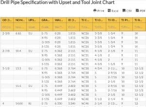
The drill pipe with upset is manufactured through a forging process where the tube ends are made with thicker walls. The process starts by heating the ends of the tube, followed by pressure application utilizing a closed die hydraulic forging press, which will create the upsets. An external upset part with an outer taper is formed on one end of the steel tube through upsetting and pressing. Internal upset forging may then be initiated by displacing the outer taper to an internal upset part with an internal taper. This is done by pressing the external upset portion. An internal upset die can deliver the final part of the internal upset forging process. Not all drill pipes are upset. This is secondary to the expenses required to successfully produce drill pipe with upset. The Tool joints of the drill pipe are the enlarged and threaded ends of drill pipe joints. Drill pipe with tool joints and the pipe body are produced separately and are welded in the end. These are made to tolerate severe working conditions of drilling, delivering connections with high-strength and high-pressure threads. Drill Pipe with Upset and Tool Joint TypesDrill pipe with tool joints can be determined by their configuration or upset on both ends. The upset of the drill pipe allows welding of the tool joints and can be categorized as:
Drill Pipe with Upset and Tool Joint AdvantagesDrill pipe with upset provides three key advantages: (1) presence of a thicker and sturdier weld area; (2) better transition from harder tool joints to more flexible pipes; and (3) stressed areas being kept away from the weld region. Drill Pipe Specification with Upset and Tool Joint Chart
Drill Pipe Specification with Upset and Tool Joint Chart
Drill Pipe Specification with Upset and Tool Joint Chart Abbreviations:
The drill pipe specifications with upset and tool joints provides data on the pipe body and tool joints. The pipe body details include:
The tool joint details include:
Go here if you are looking for the Drill Rod Thread Compatibility Chart. The Oilfield Equipment related post Drill Pipe Specification with Upset and Tool Joint Chart is from Flowtech Energy. Looking for Oilfield Equipment including New, Used, Remanufactured and Surplus Oilfield Supply, check out our inventory or call our toll free number at 877-645-6693 for more information. from https://www.flowtechenergy.com/charts/drill-pipe-specification-with-upset-and-tool-joint-chart/
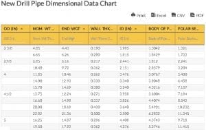
The drill pipe is an industrial tubular used in ground drilling. Its most common use is in the oil and gas industry where lengths of drill pipe are screwed together and collectively referred to as the drill string. The drill bit at the bottom of the drill string is responsible for the actual underground boring. Drill pipe is often pushed to extreme depths and therefore endures the toughest subterranean conditions. Drill pipe is compliant with the specifications developed by organizations such as the American Petroleum Industry (API). These specifications include the steel’s mechanical properties, the manufacturing details, and the new drill pipe dimensional data. Such dimensions are the external and internal diameters, the upset dimensions for the nominal size, the weight and grade, and the wall thickness. New Drill Pipe ClassificationsBecause of the working conditions that drill pipe is subjected to, it has to be carefully and regularly monitored for wear and tear. An instrument used to assess the drill pipe, particularly the sphere’s radius, is a spherometer. Under the Recommended Practice 7G guidelines established by API, new drill pipe classifications include the following: New Pipe This pipe has not been used and therefore is at its strongest grade. Premium Pipe The premium pipe is lower than the N-class pipe and endured some uniform wear but still functions favorably. It must have 80% minimum wall thickness. Class 2 Pipe All wear must be on one side of the pipe, with the cross-sectional area being the same as the premium pipe, which has no more than 20% reduction on the uniform wall. The minimum thickness on the new specified wall should not be less than 65%. Class 3 pipe The pipe must have a minimum wall thickness of 55% and the wear must all be on one side. Under Class 2 Pipe and Class 3 Pipe, the drill pipe is approaching its well-worn stage. Once the pipe has reached the end of its serviceable life, it is graded as scrap. However, as pipes are very costly, they can be sold as used and can be reused based on the above categories. New Drill Pipe Dimensional Data ChartThe New Drill Pipe Dimensional Data Chart below is based on API RP 7G and presents the following dimensions of new drill pipe under each column: the size of external diameter (D), wall thickness and internal diameter (ID) expressed in inches; the nominal weight with threads and couplings and the plain-end weight in pounds per foot, the section area of the pipe (A) in square inch, and the polar sectional modulus (Z) in cubic inches. New Drill Pipe Dimensional Data Chart
New Drill Pipe Dimensional Data Chart
New Drill Pipe Dimensional Data Chart Abbreviations:
Go here if you are looking for the Used Premium Drill Pipe Torsion, Tensile and Pressure Data Chart. The Oilfield Equipment related post New Drill Pipe Dimensional Data Chart is from Flowtech Energy. Looking for Oilfield Equipment including New, Used, Remanufactured and Surplus Oilfield Supply, check out our inventory or call our toll free number at 877-645-6693 for more information. from https://www.flowtechenergy.com/charts/new-drill-pipe-dimensional-data-chart/
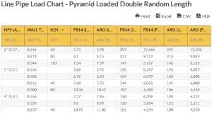
Line pipe are used to transport liquid like gas, oil, and petroleum. Thus, these line pipe are manufactured to withstand great pressures, as their use in the production of resources requires them to handle different amounts of tension. They are designed to have high strength and durability to carry a variety of loads. The sizes and diameters of these line pipe consequently vary, as the amount of gas or liquid intended for the pipes vary as well. Line Pipe LoadDifferent loads on piping systems are identified so that line pipe will be able to withstand varying amounts of pressure. For example, the primary load on a line pipe system includes external pressure, internal fluid pressure, and gravity. Secondary loads include pressures that result from displacement due to thermal movements within the pipe. Given these dynamics between pipe, pressures, and the resulting loads and sizes of pipe, the Line Pipe Load Chart serves as a guide to determine the number of pipes that will fit inside a truck in the arduous task of transporting them. (The truck type is specified in the chart below.) Line Pipe Load Chart - Pyramid Loaded Double Random Length
Line Pipe Load Chart - Pyramid Loaded Double Random Length
Line Pipe Load Chart - Pyramid Loaded Triple Random Length
Line Pipe Load Chart - Pyramid Loaded Triple Random Length
Line Pipe Load Chart - Strip Loaded Double Random Length
Line Pipe Load Chart - Strip Loaded Double Random Length
Line Pipe Load Chart - Strip Loaded Triple Random Length
Line Pipe Load Chart - Strip Loaded Triple Random Length
Line Pipe Load Chart Abbreviations
Line Pipe Load Chart SpecificationsIn the Line Pipe Load Chart, a number of key terms are featured: (1) STD wall, (2) XH wall, (3) pyramid loaded, (4) strip loaded, (5) double random lengths, (6) triple random lengths, (7) nominal pipe size, and (8) wall thickness. The STD wall and XH wall are basically two of the most common abbreviations used in the line pipe industry. This is because they stand for sizing specifications of such pipe. Simply, they mean “standard” and “extra heavy”, respectively. These specifications also determine the wall thickness of the pipe. Next, it is important to note the difference between pyramid loaded and strip loaded. Pyramid loaded refers to transportation from the warehouse to the jobsite. AS the pipe are positioned within the grooves of one another, pyramid loaded transport offers maneuverability and addresses the risk of the pipes rolling. Strip loaded, on the other hand, refers to transportation from yard to yard, as the pipe can be loaded or unloaded in larger quantities using forklifts. The double and triple random lengths basically refer to the length of the pipe from one to another. Lastly, the nominal pipe size refers to the set of standard sizes used for pipe. Go here if you are looking for the Line Pipe Size and Weight Chart. The Oilfield Equipment related post Line Pipe Load Chart (API 5L) is from Flowtech Energy. Looking for Oilfield Equipment including New, Used, Remanufactured and Surplus Oilfield Supply, check out our inventory or call our toll free number at 877-645-6693 for more information. from https://www.flowtechenergy.com/charts/line-pipe-load-chart-api-5l/
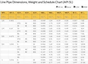
Line Pipe Dimensions, Weight and Schedule Table AnalysisThe Table for Line Pipe Dimensions, Weight and Schedule shows the six columns for pipe size, outer diameter, inner diameter, schedule, wall and weight (in pounds and feet). For each pipe size, there are corresponding dimensional values. The Line Pipe Dimensions Table also shows that an increment in pipe size raises the wall thickness or schedule and weight. On the other hand, a decrease in pipe schedule is correlated with increased inner diameter, while the outer diameter remains constant. Line Pipe Dimensions, Weight and Schedule Chart (API 5L)
Line Pipe Dimensions, Weight and Schedule Chart (API 5L)
Line Pipe Dimensions: Definition of TermsAmerican Petroleum Institute (API) API is the US trade association for the oil and natural gas industry. American Society of Mechanical Engineers (ASME) ASME is a US professional association for mechanical engineers. It is headquartered in New York. American National Standards Institute (ANSI) ANSI is a non-profit organization that promotes conformity across multiple industries. Double-extra-strong Pipe Pipe with its wall thickness increased above that of the standard-weight pipe to provide extra strength. Electric Resistance Welding Pipe (ERWP) ERWP is a type of pipe made by heating and pushing solid round steel and then shaping the steel into a hollow tube. Extra Strong Pipe Pipe with a wall thickness greater than that of the standard-weight-pipe. Doubled Submerged Arc Welded (DSAW) DSAW is pipe made from a raw material steel plate and produced by extruding through a process called double-sided merged arc welding. Size or Nominal Pipe Size The Nominal Pipe Size (NPS) refers to the North American standard for pipes used in high or low temperatures and pressures. NPS pertains only to the outer diameter or OD. The Outer Diameter remains unchanged while the wall thickness increases with larger Schedules. When NPS increases, the OD also increases. In practice, size defines the pipe wall thickness and pipe nominal diameter. Inner Diameter Also called bore diameter, the inner diameter starts from the left to the right side of the pipe’s inner interior. Outside Diameter The outer diameter is the distance from the outer wall to the other side, from top to bottom, and from left to right. Schedule Schedule refers to the wall thickness of the pipe. In the past, wall thickness was classified as Standard (STD), Extra Strong (XS) and Double Extra Strong (XXS). STD is similar to schedule 40. Standard Pipe Standard pipe refers to the schedule based on wall thickness and nominal pipe size, which in turn is based on the diameter that is measured in inches. Line Pipe Dimensions, Weight and Schedule Chart Abbreviations:
Go here if you are looking for the Line Pipe Load Chart (API 5L). The Oilfield Equipment related post Line Pipe Dimensions, Weight and Schedule Chart (API 5L) is from Flowtech Energy. Looking for Oilfield Equipment including New, Used, Remanufactured and Surplus Oilfield Supply, check out our inventory or call our toll free number at 877-645-6693 for more information. from https://www.flowtechenergy.com/charts/line-pipe-dimensions-weight-and-schedule-chart-api-5l/
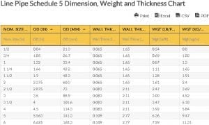
Line Pipe Schedule BasicsLine pipe schedule defines the wall thickness of the pipe. In a certain nominal pipe diameter, the outside diameter of the pipe is similar to all the schedules. Schedule of the pipe is derived from the specifications set by the American National Standards Institute (ANSI), American Society of Mechanical Engineers (ASME) B36.10M, and American Petroleum Institute (API) 5L. Line pipe schedule uses 11 number representations, where 5 is the first and lowest, and 160 is the last and highest. An increasing number reflects the progression of the wall thickness. The actual wall thickness may vary among various sized pipe, even with the same line pipe schedule. Line Pipe Schedule CalculationThe line pipe schedule number was introduced by the ASME committee based on Barlow’s thickness formula. The line pipe schedule number shows an estimated value of the expression 1000 x P / S where: P means service pressure, and S means allowable stress, both stated in pounds per square inch. An increase in the service pressure means an increase in the line pipe schedule number, which designated the pipe wall thickness. Line Pipe Schedule SignificanceCarrying fluid in various forms, like liquid gas or fluidized solids, is the primary function of line pipe. With this, oil and gas industry operators have to constantly ensure that the line pipe in use can withstand the fluid pressure. Hence, it is vital that the schedule of the line pipe, representing its wall thickness and implying its strength, be considered as a significant factor. Pipe schedule with a high denomination is expected to endure extreme pressure. Pipe material also plays a role in determining the allowable stress, along with the line pipe schedule. Therefore, for the same line pipe material, the higher the schedule of the line pipe or wall thickness is, the higher the level of stress it can tolerate. Line Pipe Schedule 5 Dimension, Weight and Thickness Chart
Line Pipe Schedule 5 Dimension, Weight and Thickness Chart
The wall thickness related to a certain line pipe schedule rests on the nominal pipe size. Other specifications such as dimensions, including outside diameter (OD), inside diameter (ID), wall thickness (WT), and schedule number of the line pipe, along with the weight, are established by ASME standards. The chart above presents the line pipe schedule 5 dimension, weight, and thickness, where the nominal size, OD, and WT are expressed both in inches (in) and millimeter (mm), and the weight in both pound per foot (lb/ft) and kilogram per meter (kg/m). Line Pipe Schedule 5 Dimension, Weight and Thickness Chart Abbreviations:
Go here if you are looking for the Line Pipe Schedule 10 Dimension, Weight and Thickness Chart. The Oilfield Equipment related post Line Pipe Schedule 5 Dimension, Weight and Thickness Chart is from Flowtech Energy. Looking for Oilfield Equipment including New, Used, Remanufactured and Surplus Oilfield Supply, check out our inventory or call our toll free number at 877-645-6693 for more information. from https://www.flowtechenergy.com/charts/line-pipe-schedule-5-dimension-weight-and-thickness-chart/
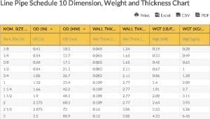
Line pipe are essential tools in the petroleum industry. They are of vital importance to the oil production process as well as to other operations that require the transport of gas or liquid. As they have a variety of uses, they are manufactured in different sizes or dimensions. As a result of these differences, line pipe vary in areas like weight and thickness but are nonetheless made to be durable enough to withstand great amounts of pressure. Thus, different specifications are made to identify these line pipe especially for the variety of clients that may need them. One of these specifications is the line pipe schedule. Line Pipe ScheduleThe line pipe schedule describes the thickness of the wall of the pipe as well as its inside diameter. Aside from describing the size of the tubing, the line pipe schedule can be used to classify the line pipe for different amounts of pressure (high or low) and for different amounts of temperature. What is important to note is that as the number of the schedule increases, the wall thickness becomes greater. While the schedule number may be the same for different sizes of pipe, the actual wall thickness may be different. One of these line pipe schedule numbers is line pipe schedule 10 as seen on the Line Pipe Schedule 10 Dimension, Weight and Thickness Chart. Line Pipe Schedule 10 Dimension, Weight and Thickness Chart
Line Pipe Schedule 10 Dimension, Weight and Thickness Chart
Line Pipe Schedule 10 Dimension, Weight and Thickness Chart Terms:In the Line Pipe Schedule 10 Dimension, Weight and Thickness Chart, there are four key terms: 1. nominal size (in inches), 2. outside diameter (both in inches and millimeters), 3. wall thickness (both in inches and millimeters), and 4. weight (both in pounds per feet and kilograms per meter). The nominal size is used as the primary specification for the pipe, as its value is based on a set of non-specific standard sizes for line pipe. Along with the ‘universal nominal size’, the outside diameter is used to specify the line pipe because it determines the overall dimensions and capacity of a line pipe. The two remaining terms on the Line Pipe Schedule 10 Dimension, Weight and Thickness Chart–the wall thickness and weight–are basically factors that depend on the nominal size and outside diameter that are specified to identify the strength of the line pipe. Line Pipe Schedule 10 Dimension, Weight and Thickness Chart Abbreviations:
Go here if you are looking for the Line Pipe Schedule 20 Dimension, Weight and Thickness Chart. The Oilfield Equipment related post Line Pipe Schedule 10 Dimension, Weight and Thickness Chart is from Flowtech Energy. Looking for Oilfield Equipment including New, Used, Remanufactured and Surplus Oilfield Supply, check out our inventory or call our toll free number at 877-645-6693 for more information. from https://www.flowtechenergy.com/charts/line-pipe-schedule-10-dimension-weight-and-thickness-chart/
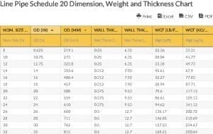
Line pipe is of much use in the petroleum industry. Evidently, they are of vital importance in the oil production process as well as in other operations that require the transport of gases or liquids moving with great pressure. As they have a variety of uses, they are also manufactured in different sizes or dimensions. As a result of these differences, line pipe varies in areas like weight and thickness but is nonetheless made to be durable to withstand great amounts of pressure. Thus, different specifications are made to differentiate and identify this line pipe especially for the variety of clients who may need them. One of these specifications is the line pipe schedule. Line Pipe ScheduleThe line pipe schedule is basically used to describe the size of the line pipe. The schedule number relates to the wall thickness of the pipe such that when the number of the schedule increases, the wall thickness becomes greater, too. Thus, the line pipe schedule defines the strength of the pipe used. It is important to note that while the schedule number may be the same for different sizes of pipes, the actual wall thickness may be different. The line pipe schedule number is defined as a result of the internal working pressure in the line pipe and the allowable stress for the material used in the construction. One of these line pipe schedule numbers is line pipe schedule 20, as seen on the diagram below, entitled Line Pipe Schedule 20 Dimension, Weight, and Thickness Chart. Line Pipe Schedule 20 Dimension, Weight and Thickness Chart
Line Pipe Schedule 20 Dimension, Weight and Thickness Chart
Line Pipe Schedule 20 Dimension, Weight and Thickness Chart Abbreviations:
Line Pipe Schedule TermsIn the Line Pipe Schedule 20 Dimension, Weight and Thickness Chart, there are four key terms used:
The wall thickness and weight are factors that depend on the nominal size and outside diameter that are specified. They identify the strength of the line pipe. Go here if you are looking for the Line Pipe Schedule 5 Dimension, Weight and Thickness Chart. The Oilfield Equipment related post Line Pipe Schedule 20 Dimension, Weight and Thickness Chart is from Flowtech Energy. Looking for Oilfield Equipment including New, Used, Remanufactured and Surplus Oilfield Supply, check out our inventory or call our toll free number at 877-645-6693 for more information. from https://www.flowtechenergy.com/charts/line-pipe-schedule-20-dimension-weight-and-thickness-chart/ |
About UsOur goal and our mission is to provide a solid and dependent structure to support your companies needs. We have over thirty years supplying and supporting industrial drilling equipment for companies around the world. In order to support and provide the best customer experience we focus on you, the customer, to offer a full turnkey solution for whatever your business needs. Our products fused with our customer service will bring you a sophisticated, well oiled business process that can fit any business need. ArchivesNo Archives Categories |

 RSS Feed
