|
Pipes used in the drilling of gas and oil wells are meant for carrying fluid under certain kinds of pressure from internal or external factors, sometimes both. To withstand fluid pressure and for the pipes to carry out their functions efficiently, they must be made sufficiently stronger. The strength of pipes depends mainly on wall thickness. The necessity to use pipes that can sustain pressurized fluid led to the development of standard pipe sizes. Decades ago, line pipe sizes were limited to three standards: Extra-Strong (XS), Standard Weight (STD), and Double Extra Strong (XXS). With modernization, there was a need to develop other standards to meet the changing requirements dictated by the industry. Pipe SchedulePipe schedule basically describes a pipe’s thickness and is identified by the abbreviation SCH. Under the standard API 5L and ANSI/ASME B36.10 M, the most common schedules consist of the following: 5, 10, 20, 30, 40, 60, 80, 100, 120, 140 and 160. The most popular of the line pipe schedules is 40 while 5, 60, 100, 120 and 140 are seldom used. Line Pipe Comparative Sizes, Schedules and Wall ThicknessPipe size is normally the Nominal Pipe Size (NPS), so for a 6-inch pipe, 6 inches is its nominal size. For NPS 14 and above, the outside diameter (OD) will be the same as the NPS. The OD for all pipe sizes is fixed. When the schedule or wall thickness varies, this has an implication on the inside diameter (ID). An increase in the schedule number increases the wall thickness but inversely reduces the actual bore. This makes the ID almost equal to the pipe’s nominal size. Line Pipe Schedule 60 Dimension, Weight and Thickness Chart
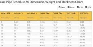
Line Pipe Schedule 60 Dimension, Weight and Thickness Chart
The Line Pipe Schedule 60 Dimension, Weight and Thickness Chart shown above includes dimensional measurements in inches and millimeters. Weight is expressed in either pounds per foot or kilogram per meter. The schedule number is determined using the following equation: Schedule Number = (1,000) (P/S), where: P – indicates the internal working pressure in pounds per inch, and Line Pipe Schedule 60 Dimension, Weight and Thickness Chart Abbreviations:
Line Pipe Standard SpecificationsThe manufacture of line pipe follows the most common specifications developed by organizations responsible for standardizations:
API stands for the American Petroleum Institute while ASME stands for the American Society of Mechanical Engineers and ANSI refers to the American National Standards Institute. Go here if you are looking for the Line Pipe Schedule 80 Dimension, Weight and Thickness Chart. The Oilfield Equipment related post Line Pipe Schedule 60 Dimension, Weight and Thickness Chart is from Flowtech Energy. Looking for Oilfield Equipment including New, Used, Remanufactured and Surplus Oilfield Supply, check out our inventory or call our toll free number at 877-645-6693 for more information. from https://www.flowtechenergy.com/charts/line-pipe-schedule-60-dimension-weight-and-thickness-chart/
0 Comments
The line pipe’s major function in the oil and gas industry is the transmission or conveyance of fluids. Generally, the transport of fluid is conducted under a certain level of pressure which makes the internal diameter (ID) a critical line pipe dimension. The ID changes with the wall thickness of the pipe such that as the wall thickens, it effectively decreases the ID. While certain schedules have the same outside diameter, which is fixed, they correspond to a series of different wall thicknesses which are necessary to bear the fluid’s pressure during transmission. Such are shown in the chart of line pipe schedule 80 dimension, weight, and thickness. Pipe SchedulesThe pipe schedules available in the market are manufactured based on specifications that are compliant with standards set by organizations such as the Association of American Mechanical Engineers (ASME). The pipe can be seamless, welded wrought steel, or the costlier stainless steel. The schedules are presented as numbers prefixed by SCH and suffixed with the letter ‘S’ if this is stainless steel pipe. The most commonly used are pipe schedule 40 and 80; they are manufactured in large volume or quantities. While these are the most in-demand schedules, the latter is thicker than the former. The features of pipe schedule 80 are outlined in the line pipe schedule 80 dimension, weight, and thickness table shown below. Simply put, the larger the number is, the thicker the surface wall and the higher the pipe’s resistance become. The schedule number is computed by coming up with an approximate value using the following formula: Schedule Number = P/S x 1000 Where: P stands for design pressure, while S is the allowable stress of material expressed in pounds per square inch or psi. Line Pipe Schedule 80 Dimension, Weight and Thickness Chart
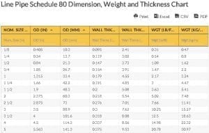
Line Pipe Schedule 80 Dimension, Weight and Thickness Chart
Pipe DimensionsBased on the above chart, steel pipe’s dimensions include the outer diameter or OD, wall thickness or WT, and length which ranges from 20 ft or 6 meters to 40 ft or 12 meters. Given these dimensions, the weight of the pipe, the amount of pressure it can withstand, and its cost per foot or meter can be calculated. Pipe dimensions can be expressed as follows:
Line Pipe Schedule 80 Dimension, Weight and Thickness Chart Abbreviations:
Go here if you are looking for the Line Pipe Schedule 30 Dimension, Weight and Thickness Chart. The Oilfield Equipment related post Line Pipe Schedule 80 Dimension, Weight and Thickness Chart is from Flowtech Energy. Looking for Oilfield Equipment including New, Used, Remanufactured and Surplus Oilfield Supply, check out our inventory or call our toll free number at 877-645-6693 for more information. from https://www.flowtechenergy.com/charts/line-pipe-schedule-80-dimension-weight-and-thickness-chart/
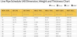
The schedule number (140) is equivalent to the pressure and stress that are both measured in pounds per square inch (psi). Schedule number = p/s P – the service pressure Line Pipe Schedule 140 Dimension, Weight, and Thickness ChartThe Line Pipe Schedule 140 Dimension, Weight, and Thickness Chart shows the exact numerical values for each nominal size and corresponding dimensions (diameter, thickness) and weight. The chart or table is useful for specifying the best pipe for drilling completion. It allows one to determine the pipe that is compatible with other drill pipe components, as well as the pipe that is best for certain underground conditions. Line Pipe Schedule 140 Dimension, Weight and Thickness Chart
Line Pipe Schedule 140 Dimension, Weight and Thickness Chart
Line Pipe SCH 140: Definition of Dimensional ValuesThe Table for Line Pipe Schedule 140 Dimension, Weight, and Thickness constitutes rows for nominal sizes and columns for dimensional values. Nominal size is the non-specific term used for non-approximate values. It refers to the outside diameter. A 2 nominal pipe size means a pipe with 2.375 inches on its outside diameter regardless of wall thickness. An increase in the schedule (SCH) increments the mechanical pipe strength and allows it to withstand higher pressures. Outside diameter is the measurement from the outer wall to the other side – top to bottom and left to right. To calculate the outside diameter, use this formula: Outside diameter = ID + Wall thickness (2x) Wall thickness is expressed in pipe schedule. The wall thickness measures the pipe’s wall in inches or millimeters. To calculate the wall thickness based on ID and OD, here is the formula: Wall thickness = ID – OD / 2 Weight defines the pipe’s weight per foot or pound. Line Pipe Schedule 140 DimensionsThe Line Pipe Schedule 140 Dimension, Thickness, and Weight Table shows that an increase in nominal size also increments the outside diameter (millimeters), wall thickness (inches and millimeter), and weight (kg/m) except for the outside diameter. For example, in stainless steel pipes and tubes, the formula for Outer Diameter would be the following: OD (mm) – W.T (mm) X W.T (mm) x 0.02466 = kilogram per meter. Line Pipe Schedule 140 Dimensions Chart Abbreviations:
Go here if you are looking for the Line Pipe Schedule 160 Dimension, Weight and Thickness Chart The Oilfield Equipment related post Line Pipe Schedule 140 Dimension, Weight and Thickness Chart is from Flowtech Energy. Looking for Oilfield Equipment including New, Used, Remanufactured and Surplus Oilfield Supply, check out our inventory or call our toll free number at 877-645-6693 for more information. from https://www.flowtechenergy.com/charts/line-pipe-schedule-140-dimension-weight-and-thickness-chart/
Line Pipe Schedule 160 Dimension, Weight and Thickness Chart contains fact-based information on line pipe. Specific structural data about the line pipe is valuable as they represent the pipe’s strength, limitation, and suitability to certain situations. Line pipe schedules are commonly used to determine the thickness of the pipe. In the pipe industry, as the figure increases, so does the pipe’s diameter. While the pipe schedule can be similar with various pipe sizes, its thickness still varies. Line Pipe Schedule 160 Dimension, Weight, and Thickness DiscussionThe function of the pipe is to carry and transport fluid from its source area. Given this, the pipe’s internal diameter is considered a critical dimension. In the past, there were three pipe wall thickness standards being followed:
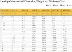
However, these were not suitable for all the applications. The pipe chart has been revised and international institutions came up with pipe schedules. There are now 11 schedule numbers typically used: 5, 10, 20, 30, 40, 60, 80, 100, 120, 140, and 160. These are the standards given by prominent institutions such as ANSI (American National Standards Institute), ASME (American Society of Mechanical Engineers), and API (American Petroleum Institute). SCH 40 is popular and preferred more for pipe that measures 8 inches or below, while pipe schedules 5, 60,100, 120 and 140 are rarely utilized. Certain factors are considered first when pipe is involved in a project. In the revised pipe chart, STD is equivalent to SCH for NPS 10 while XS is identical to pipe schedule 80 for NPS 8. The strongest and most efficient is comparable to SCH 160 from NPS 60. The schedules are usually calculated using this expression: SCH Number = (1,000) (P/S) P – the internal pressure S – the stress that is allowed for the material Line Pipe Schedule 160 Dimension, Weight and Thickness Chart
Line Pipe Schedule 160 Dimension, Weight and Thickness Chart
Line Pipe Schedule 160 Dimension, Weight and Thickness Chart Abbreviations:
In this Line Pipe Schedule 160 Dimension, Weight, and Thickness Chart, the factors that comprise the line pipe dimension 160 are presented. These are used to determine the diameter of the pipe for different industrial purposes. Nominal Pipe Size is an international standard implemented to follow specific pipe diameter and thickness. Line Pipe Dimensions & Weight Metrication
Go here if you are looking for the Line Pipe Schedule 120 Dimension, Weight and Thickness Chart. The Oilfield Equipment related post Line Pipe Schedule 160 Dimension, Weight and Thickness Chart is from Flowtech Energy. Looking for Oilfield Equipment including New, Used, Remanufactured and Surplus Oilfield Supply, check out our inventory or call our toll free number at 877-645-6693 for more information. from https://www.flowtechenergy.com/charts/line-pipe-schedule-160-dimension-weight-and-thickness-chart/
Welded and Seamless Steel Pipe Schedule Weight DiscussionThe line pipe manufacturing industry produces two types of pipe: welded steel pipe and seamless steel pipe. They have significant differences in terms of production cost and steel grade. Welded steel pipe is used widely in automobiles, boilers, furniture, scaffolding, and other industries. This steel pipe is a tubular material that is made from flat plates, known as skelp that is formed to prepare for welding. To ensure high-quality standards, a radiological or ultrasonic inspection is performed together with a pressure test. Listed below are the benefits of using welded steel pipe:
Meanwhile, seamless line pipe is made from a cylindrical bar heated to a high temperature before piercing it to make a hole through the cylinder. The roller sizes are used to create the pipe’s wall thickness and correct diameter. The process creates small diameter pipe ranging from 0.5 to 24 inches. Here are some benefits of using seamless line pipe:
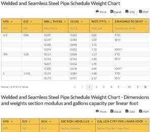
Increased pressure rating is the seamless line pipe’s best benefit, as it has increased ability to resist heavy loads. While it is a bit expensive, lighter and thinner sizes can be an option to reduce the expenses. Welded and Seamless Steel Pipe Schedule Weight Chart
Welded and Seamless Steel Pipe Schedule Weight Chart
Welded and Seamless Steel Pipe Schedule Weight Chart - Dimensions and weights section modulus and gallons capacity per linear foot
Welded and Seamless Steel Pipe Schedule Weight Chart - Dimensions and weights section modulus and gallons capacity per linear foot
Terms Used:Nominal pipe size is an international standard used to determine the diameter of a certain pipe. Pipe schedule defines a pipe’s wall thickness. Examples include SCH: 5, 10, 20, 30, 40, 60, 80, 100, 120, 140, and 160. O.D = Outside diameter I.D = Inside diameter wall = Wall thickness lbs/ft = lbs/ft STD = Standard weight. Welded and Seamless Steel Pipe Schedule Weight Chart Abbreviations:
Pipe Size Formula:
Go here if you are looking for the Line Pipe Dimensions and Schedule in Millimeters Chart (API 5L). The Oilfield Equipment related post Welded and Seamless Steel Pipe Schedule Weight Chart is from Flowtech Energy. Looking for Oilfield Equipment including New, Used, Remanufactured and Surplus Oilfield Supply, check out our inventory or call our toll free number at 877-645-6693 for more information. from https://www.flowtechenergy.com/charts/welded-and-seamless-steel-pipe-schedule-weight-chart/
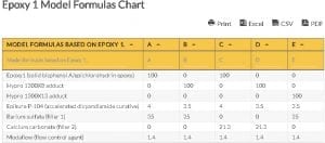
Epoxy 1 Model Formulas Table AnalysisThe Table for Epoxy 1 Model Formulas shows the weight percentage per sample as shown in letters. Each letter in the column represents the formulations or model formulas, and the parts per weight. For instance, Formula A has 100 parts per Epoxy 1 modified with Epikure P-104, Barium sulfate (filler 1), unmodified with Calcium carbonate (filler 2), and modified with Modaflow (flow control agent). The same formulation applies to the other columns. The Epoxy 1 Model Formulas and Table shows that adducts, fillers, and additives can improve or affect the epoxy powder coating’s flexibility, resistance, performance, and durability. Epoxy 1 Model Formulas Chart
Epoxy 1 Model Formulas Chart
Legend: A, B, C, D, E – represent the various model formulas Epoxy 1 Model Formulas Chart: Definition of TermsEpoxy Epoxy consists of a hardener and an epoxy resin that, when mixed together in a proper formulation or combo, will produce a hard, solvent, and chemical-resistant finish. Epoxies are used in pipes, stones, metals, woods, and painted and veneer surfaces. Filler Filler is an epoxy used to thicken the primer epoxy, fill dings and gaps, and smooth or level surfaces. Flow Control Flow control Is an epoxy agent used to ensure the proper spreading of the epoxy onto the surface without any fish eye, cratering, or surface defect. Powder CoatingsPowder coating is an adhesive applied through the electrostatic spray deposition or ESD. The powder can be a thermoset or thermoplastic polymer (a plastic material). The following are the various types of powder coatings: Solid Bisphenol A This is an organic compound that is crystalline and a colorless solid. The material is often used in containers, epoxy resins, adhesive coatings, and electrical insulation. Epichlorohydrin Epoxy This Is a pungent, sweet, and colorless liquid used for making epoxy resins. Hypro 1300X8 Adduct This is an acrylonitrile copolymer – carboxyl terminated butadiene—that is used as a reactant to improve epoxy performance. Adduct means the result of addition reaction. Hypro 1300X13 Adduct This is a carboxyl terminated butadiene or CTBN epoxy toughener. It is used as a reactant with a base. Epikure P-104 (Accelerated Dicyandiamide Curative) This is a trademark that refers to a curing agent and powder epoxy curing agent. Barium Sulfate (Filler 1) This is a transparent inorganic compound that is used to change consistency or can become a filler. Barium sulfate is also used as pigment. Calcium Carbonate (Filler 2) This is a filler and pigment. It has the largest volume filler that is often used in plastic applications. Modaflow (Flow Control Agent) This is an additive used without adding silicone. It’s used for latex, water-reducible, and dispersion systems. Go here if you are looking for the Coating Thickness Conversion Chart. The Oilfield Equipment related post Epoxy 1 Model Formulas Chart is from Flowtech Energy. Looking for Oilfield Equipment including New, Used, Remanufactured and Surplus Oilfield Supply, check out our inventory or call our toll free number at 877-645-6693 for more information. from https://www.flowtechenergy.com/charts/epoxy-1-model-formulas-chart/
The pipe is usually coated with Epoxy substances to prevent corrosion. It is important that this coating is durable as well as flexible to make the pipe efficient for the transport of oil and gas. The Epoxy 2 Model Formulas Chart presents model formulas for power coatings that are based on Epoxy 2. In general, an epoxy is an organic compound that is made of carbons linked to other elements such as nitrogen, hydrogen, or oxygen. As a result, it creates a covalent bond in which the elements share electrons to stay together. Epoxy 2 Model Formulas DiscussionAs the chart presents a model formula, it is best to discuss the specific terms used in the formula based on Epoxy 2. Solid bisphenol A/ Epichlorohydrin is also known as BPA. It is a transparent crystalline material that belongs to a family of organic compounds. This is widely used in manufacturing polycarbonate plastics and epoxy resins. C15H16O2 is its molecular formula. Novalac Epoxy is a type of resin utilized as an epoxy coating for pipe, floors, tanks, and electronic parts. The great advantage of this product is its high resistance to corrosion, chemical content, and temperature. Hypro 1300X8 is a globally used reactant with thermoset resin to enhance a material’s performance. Specifically, it increases the temperature mechanical properties and crack resistance. It also improves the flexibility of thermoset resins. It is commonly used for composites, film adhesives, and polymeric intermediate for vinyl esters and epoxies. Epoxy 2 Model Formulas Chart
Epoxy 2 Model Formulas Chart
Legend: F, G. H. I, J – represent the various model formulas Other Terms used in the tableBarium Sulfate (Filler 1) is a kind of inorganic compound, with BaSO4 as its chemical formula. This compound is known to be insoluble in water and is also odorless. Calcium Carbonate (Filler 2) has a huge role in formulating a sealant, adhesive, and coating compound. Its presence improves relevant properties of a material. These fillers increase abrasion resistance, thermal stability, corrosion resistance, and machinability. They also make the material flame retardant. Moreover, there are fillers that exhibit high heat dissipation characteristics and electrical conductivity. Manufacturers utilize these fillers to curtail weight and manage the viscosity while improving dimensional stability. Modaflow (flow control agent) can greatly enhance the performance and properties of a pipe system. Here are some notable advantages:
Go here if you are looking for the Epoxy 1 Model Formulas Chart. The Oilfield Equipment related post Epoxy 2 Model Formulas Chart is from Flowtech Energy. Looking for Oilfield Equipment including New, Used, Remanufactured and Surplus Oilfield Supply, check out our inventory or call our toll free number at 877-645-6693 for more information. from https://www.flowtechenergy.com/charts/epoxy-2-model-formulas-chart/
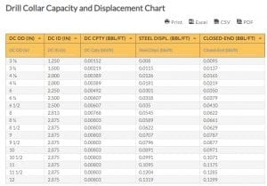
The Drill Collar Capacities and Displacement Chart shows the numerical values for outer diameter, internal diameter, capacity, and displacements. The table is useful for determining the correct drill collar type, knowing which drill collar is appropriate between the drill pipe and a bit, and finding the best drill collar for certain drilling conditions and completions in the gas and oil industry. Relationship among Internal, External Diameter, Capacity, and DisplacementsThe Displacement and Drill Collar Capacity Table shows the relationship among the dimensions, capacity, and displacements. Both capacity and displacement increase in relation to the outer diameter and inner diameter. An increase in outer diameter increases the inner diameter (in inches), but the inner diameter only changes slightly. It is possible for a pipe or drill collar to increase in outer diameter while keeping its inner diameter constant. Definition of Terms
Drill Collar Capacity and Displacement Chart
Drill Collar Capacity and Displacement Chart
The Table for Drill Collar Capacity and Displacement shows the following columns and their numerical values. Outer Diameter (in) is the measurement from the pipe’s outer wall to the other side – from top to bottom and left to right. OD = N + 2 / P Inside Diameter (in) is the measurement from the pipe’s inner wall to the other side – from top to bottom and left to right. ID = OD – Wall Thickness (2X) Where outer diameter is subtracted by wall thickness and multiplied by 2. Capacity refers to the measure of the drill collar’s internal area, expressed in length/volume, usually bbl/ft or gal/ft. Displacement is measured in gallons per feet. It pertains to the volume of fluid displaced in relation to the pipe’s volume. To calculate, here is the formula: Pipe Displacement in bbl/ft = (Outer Diameter in (2x) – Internal Diameter in (2x) – ) / 1029.4 Note: The outer diameter of the pipe (inches) and the inner diameter of the pipe are in inches. This formula is not meant for closed-end displacement. Drill Collar Capacity and Displacement Chart Abbreviations:
Go here if you are looking for the Sucker Rod Chemical, Grade and Strength Chart. The Oilfield Equipment related post Drill Collar Capacity and Displacement Chart is from Flowtech Energy. Looking for Oilfield Equipment including New, Used, Remanufactured and Surplus Oilfield Supply, check out our inventory or call our toll free number at 877-645-6693 for more information. from https://www.flowtechenergy.com/charts/drill-collar-capacity-and-displacement-chart/
The sucker rod is utilized in the oil and gas industry to connect the surface and downhole compositions of an interchanging piston pump mounted in an oil well. It is usually made of steel with threaded ends and measures from 25 to 30 feet long. A series of interconnected sucker rods connect the downhole pump deep down the well to the visible pumpjack above the ground that serves as drive for the well pump. Fiberglass sucker rods, with a metallic female thread at one end and a male thread on the other, are also available in lengths of 37 ½ feet, as well as in three-fourth- seven-eighth, one, and one-and-one-fourth- inch diameters. Aside from steel and fiberglass, sucker rod chemical, grade, and strength may vary depending on the other types:
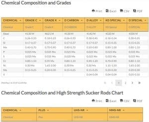
Sucker Rod BenefitsThe sucker rod is an essential part of the sucker rod pump system that plays as a basic artificial lift structure. Sucker rods, along with other parts such as the beam, crank, and other compositions, are used together to deliver a mechanical reciprocating movement. Fluids are lifted up using the sucker rod string through the mechanical motion. Sucker Rod Chemical, Grade, and Strength ChartThe Sucker Rod Chemical, Grade, and Strength Chart specifications are established through the API Spec. 11B, which presents the three primary grades of steels rods:
Chemical Composition and Grades
Chemical Composition and Grades
Chemical Composition and High Strength Sucker Rods Chart
Chemical Composition and High Strength Sucker Rods Chart
The sucker rod minimum yield strength was not specified by the API, as seen from the chart of sucker rod chemical, grade, and Strength; however, it is still needed in the computation of the rod string yield strength. Thus, it is advised that in case the manufacturer is not identified, the following standards must be used: 60,000 psi minimum yield strength for Sucker Rod Grade C and K, and 100,000 psi for Sucker Rod Grade D. Oil and gas industry operators should know that in order to maintain good operations, the minimum yield strength must be met. Go here if you are looking for the Drill Collar Weight and Bending Strength Chart. The Oilfield Equipment related post Sucker Rod Chemical, Grade and Strength Chart is from Flowtech Energy. Looking for Oilfield Equipment including New, Used, Remanufactured and Surplus Oilfield Supply, check out our inventory or call our toll free number at 877-645-6693 for more information. from https://www.flowtechenergy.com/charts/sucker-rod-chemical-grade-and-strength-chart/
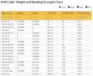
In the oil production process, line pipe is not the only tool needed for a successful wellbore. Among the materials used alongside line pipe are drill collars. Drill collars are used to provide weight on the drill bit. They are tubular pieces of a drill string, which have thick walls made of steel or special kinds of alloy. Another main function of drill collars is to provide a path for the drilling fluid that is being pumped through them. Drill Collar DynamicsA drill collar works because of the gravity that acts on it. Because of its large mass, gravity pulls down the collars and provides the downward force that drill bits need to break through the ground. Multiple collars can also be assembled together to make up what is called the bottom hole assembly. During the drilling process, the downward force provided by drill collars is built up by lowering the drill bit until it touches the bottom so that more weight is also applied to such a drill bit. Given how these drill collars work, it is of vital importance that their material provides the weight and bending strength necessary for their function. Such is shown in the Drill Collar Weight and Bending Strength Chart below. Drill Collar Weight and Bending Strength Chart
Drill Collar Weight and Bending Strength Chart
Drill Collar Weight and Bending Strength Chart TermsIn the Drill Collar Weight and Bending Strength Chart, the following key terms are listed: (1) drill collar number, (2) outside diameter measured in inches, (3) inside diameter measured in inches, (4) length in feet, (5) approximate weight in pounds per feet), and (6) typical bending strength ratio. The drill collar number is used as the main specification of the drill collar. Additional notes about this are also seen at the bottom of the table. The outside diameter and inside diameter, both measured in inches, are what describe the size of the drill collar. Aside from the circular dimensions of the collar, the length and approximate weight of the drill collar is also given in the table. The Drill Collar Weight and Bending Strength Chart shows the typical bending strength ratio. This piece of information is important because many failures in drill collar connections are a result of not being able to take into consideration the bending strength ratio. This ratio describes the relative stiffness in the drilling structure and the behavior of a connection in a “rotational cyclical environment”. Drill Collar Weight and Bending Strength Chart Abbreviations:
Go here if you are looking for the Drill Collar Capacity and Displacement Chart. The Oilfield Equipment related post Drill Collar Weight and Bending Strength Chart is from Flowtech Energy. Looking for Oilfield Equipment including New, Used, Remanufactured and Surplus Oilfield Supply, check out our inventory or call our toll free number at 877-645-6693 for more information. from https://www.flowtechenergy.com/charts/drill-collar-weight-and-bending-strength-chart/ |
About UsOur goal and our mission is to provide a solid and dependent structure to support your companies needs. We have over thirty years supplying and supporting industrial drilling equipment for companies around the world. In order to support and provide the best customer experience we focus on you, the customer, to offer a full turnkey solution for whatever your business needs. Our products fused with our customer service will bring you a sophisticated, well oiled business process that can fit any business need. ArchivesNo Archives Categories |

 RSS Feed
